
|
|
Rx65b Overview
|
|
|
|
|

|
|
|
PCB ID: 65b
PRODUCT: Rx65
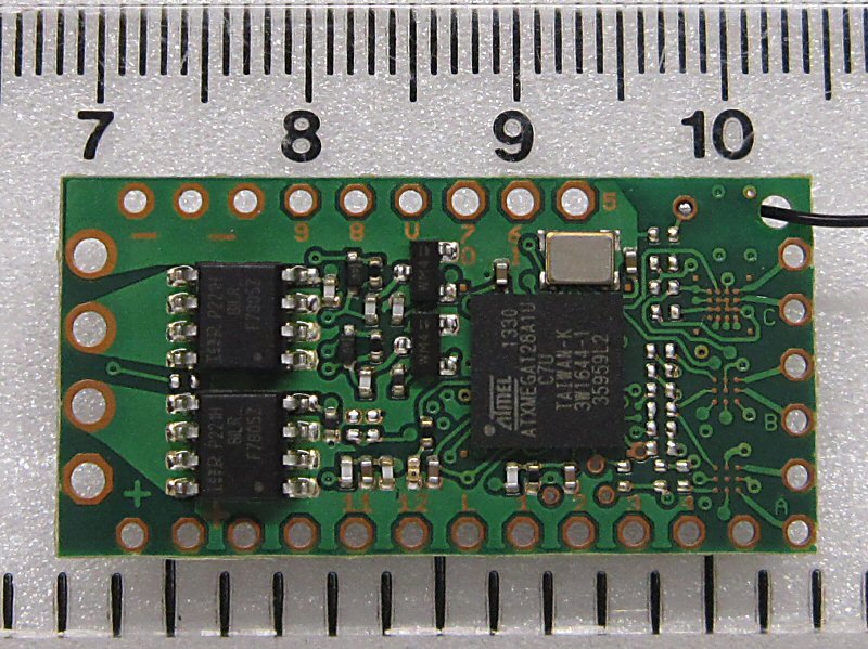
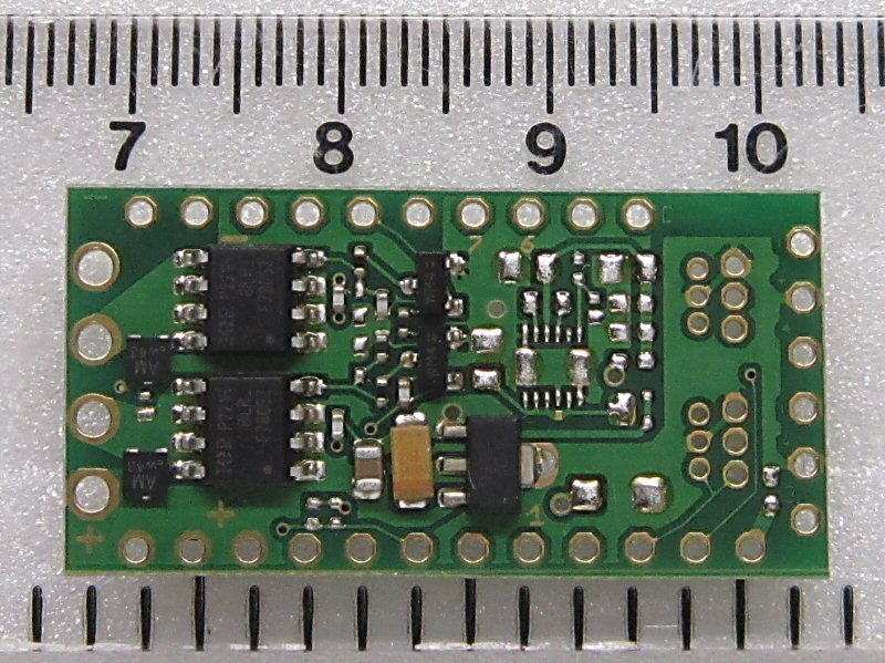
PCB SIZE: 18x35mm (0.7x1.4")
PROGRAMMING: v611
ALL FEATURES: v611
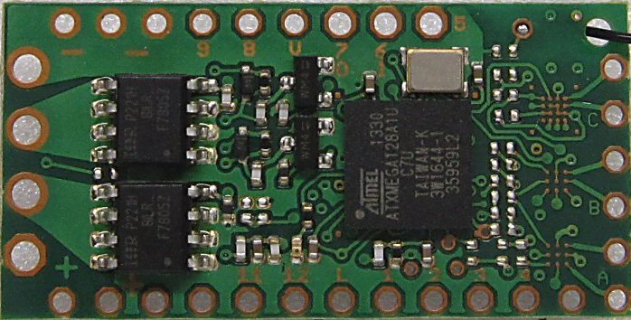
CORE RECEIVER:
2.4GHz receiver compatible with DSM2/DSMX including one integrated 3A reversable controller for brushed motors (ESC)
3-18v for 1-4S lipo, 1-5 life, 3-12 nicads, 1-2 PP3
|
Click to enlarge |
Name | GBP |
H outputs (ESC) |
P outputs (On/Off) |
F outputs (Buffered) |
Instructions (x=Variant 1-22) |
 |
Rx65-x Rx65-x-U (U=with long aerial) |
Ł40 Ł45 |
1 | 12 | 3 |
x = 1, 2, 22, 3, 4, 5, 6 |
eg: Rx65-2 (Variant 2, one 3A 18v ESC)
eg: Rx65-22 (Variant 22, one 3A 18v ESC)
eg: Rx65-22-U (Variant 22, one 3A 18v ESC, long aerial)
VARIANTS:
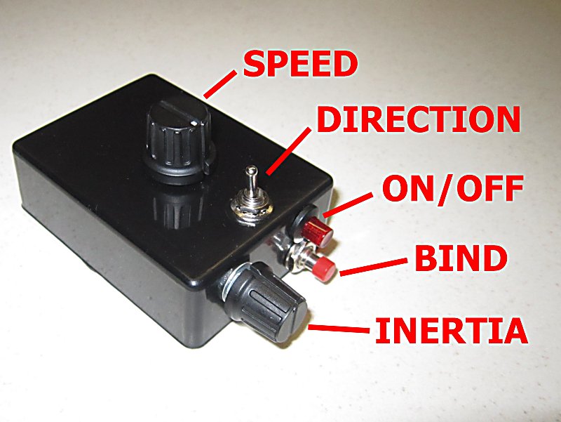
Rx65-1: Settings for 'trains' with separate controls for speed and direction
Rx65-2: As above but one control for throttle (center off)
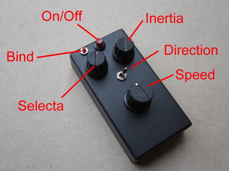
Rx65-22: As above but with Selecta enabled (for use with Tx22)
Rx65-3: Mostly servo outputs
Rx65-4: Settings for 'cars' *
Rx65-5: Settings for DX3 *
Rx65-6: Settings for 'boats' *
* 3A2 versions have 2-motor steering
OPTION:

|
U = coax aerial |
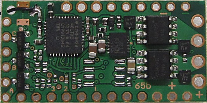
RECEIVER + DAUGHTER BOARD:
6A1 = One 6A motor output, 3A2 = Two 3A motor outputs, x = Variant, NWRSU = Options as per above
|
Click to enlarge |
Name | GBP |
H outputs (ESC) |
P outputs (On/Off) |
F outputs (Buffered) |
Instructions (x=Variant 1-22) |
 |
Rx65-x-6A1-18v Rx65-x-3A2-18v |
Ł59 Ł59 |
1 2 |
7 7 6 |
3 3 4 |
6A1: 1, 2, 22, 3, 4, 5, 6 3A2: 1, 2, 22, 3, 4, 5, 6 3-18v for 1-4S lipo, 1-5 life, 3-12 nicads One P output can be used as a fourth F output |
|
|
Rx65-x-6A1-9v-B Rx65-x-3A2-9v-B |
Ł61 Ł61 |
1 2 |
7 7 6 |
3 3 4 |
Instructions as per above but reduced voltage range B = Includes 1A 5v BEC 6-9v for 2S lipo, 2 life, 4-6 nicads, PP3 One P output can be used as a fourth F output |
eg: Rx65-4-3A2-18v (Variant 4, two 3A 18v ESC, No wires)
eg: Rx65-6-3A2-9v-BU (Variant 6, two 3A 9v ESC, BEC, Long aerial)
DAUGHTER BOARD ONLY:
The daughter board is used to add features to Rx65.
|
Click to enlarge |
Name | GBP |
H outputs (ESC) |
BEC outputs (1A 5v) |
F outputs (Buffered) |
Info |
  |
ADD3-F ADD3-FB ADD3-FH ADD3-FHB (incl. 36-way 0.1" pin header) |
Ł3 Ł5 Ł10 Ł12 |
- - 1 1 |
- 1 - 1 |
1 1 1 1 |
Fet Fet + BEC Fet + H-Bridge Fet + H-Bridge + BEC H-Bridge is 3A 18v rated, but no higher than 9v is recommended if used with a BEC installed The BEC has a 5v 1A output |
COMMENTARY:
This page is for Rx65b. Details for the previous Rx65a version can be found here.
This version of Rx65 comprises a core receiver and an optional daughter board.
Standard:
The simplest way to start is with a 'wired' version of the receiver (eg: Rx65-22 with Tx22-Built). Connect the red/back to a battery and two other wires to the motor, bind once and that's about it. Make sure you read the instructions for your variant (links above).
More advanced info:
The receiver is built with 20v components and is rated for 3-18v operation. The version marked as being '9v' is made with the 18v specification but has a BEC installed. The BEC generates too much heat at high voltages so that version is recommended for use between 6-9v. It may be possible to use it above 9v but this depends on how much current the servo draws in regular use. A BEC is a Battery Eliminator Circuit used to power servos at 5v.
'P' outputs are 'pads' with 'logic' type outputs. Pads are simply solder points for controlling external things. Logic outputs are either on or off (also known as high/low and 3.5v/0v in voltage terms). The action can be inverted so 'On' can mean 0v or 3.5v. P outputs are used to provide servo signals direct to the white/yellow lead on a servo. They can often directly control triggers on external sound cards. They are also used to drive leds but need a resistor to limit current to no more than 20mA.
'F' outputs are 'buffered' P outputs. The buffer is a fet. These provide a path to ground (0v) when on and are floating (disconnected) when off. Technically they are called 'open drain' (the equivalent with a transistor which is more widely known is called 'open collector'). Three F outputs exist on Rx65. They are labelled A, B and C. There is a fourth output 'D' available on the daughter board. It is controlled by P5 so P5 can either be used directly or in its buffered form (D). F outputs can handle up to 2A current. They are often used to control sound cards and lights.
Rx65 is intended for surface vehicles which require forward and reverse motor control. For brushed motors this is achieved with an H-Bridge. Motor outputs are abbreviated H1 and H2. These are often referred to as ESCs (Electronic Speed Controllers). They have 256 step resolution in both directions (512 total). They control speed with PWM which by default is set to its fastest (quietest) 12kHz setting.
Each H output can handle up to 3A current. This is measured with motor stalled. The main constraint with current is heat in the receiver. Higher currents may be possible if heat sinks are added or PWM frequency is reduced to 200Hz. Rx65 has one integrated ESC (H1). A daughter board can provide a second (H2) which can be used independantly ('3A2' = 3A x2) or in parallel ('6A1' = 6A x1). How the outputs are used has to be set with programming (see below). Receivers are provided 'pre-programmed'. The default settings are shown on the instructions pages for each variant.
'Variants' are simply 'configurations'. Each variant is a different combination of settings to better match common needs. Although these are described as 'car/train/boat' any variant can be used for anything. All settings can be changed in a process called 'programming'. F1-F3 are programmed as P13-P15. 'D' is controlled with P5.
Rx65 has 1xH + 12xP + 3xF outputs if is used on its own.
Rx65 has 2xH + 7xP + 3xF outputs if is used with a daughter board. H1 and H2 can be used independantly, mixed for steering, or used in parallel as one.
INSTALLING DAUGHTER BOARD:
Daughter boards are normally supplied pre-installed. However, anyone can do this if they understand what's involved. The ADD3 page describes the process.