
|
|
DT Receiver - Rx43d-2-v503 - Programming
|
1. PROGRAMMING APPROACH:
Settings in the Rx can be changed using a standard Tx. One output or feature (ie: one row in the table) is programmed at a time. Levels 1-2 usually select the output and Levels 3-5 change its characteristics.
2. PROGRAMMING OPTIONS:
|
Level 1 'H', 'F', 'P' or 'Other' |
Level 2 Output number |
Level 3 Output type |
Level 4 Channel number |
Level 5 Other choices |
Default | Information |
| 1 flash = 'H' outputs | 1-2 flash = H1-2 |
1 flash = 'Half stick' control (center off) |
1-7 flash = Channel 1-7 |
1112 1213 |
1/2 stick forward, 1/2 stick back, middle off Set 'Arming' position to 'middle' |
|
|
|
||||||
| 1 flash = 'H' outputs | 1 flash = H1 | 2 flash = 2 channel mix | 1-7 flash = 1st Ch 1-7 |
1 flash = 0% mix 2 flash = 12.5% mix 3 flash = 25% mix 4 flash = 50% mix 5 flash = 100% mix |
H1/H2 used as a pair (middle off) Set 'Arming' position to 'middle' |
|
| 1 flash = 'H' outputs | 2 flash = H2 | 2 flash = 2 channel mix | 1-7 flash = 2nd Ch 1-7 | H1/H2 used as a pair | ||
|
|
||||||
| 1 flash = 'H' outputs | 1-2 flash = H1-2 |
3 flash = 'Full stick' control (can only use with 1 output) |
1-7 flash = Primary Ch 1-7 | 1-7 flash = Direction Ch 1-7 |
Low stick 0%, full stick 100% 'Direction' channel toggles forward/reverse (when 'Primary' channel is 0%) Set 'Arming' position to 'low' |
|
|
|
||||||
| 2 flash = 'F' outputs | 1-2 flash = F1-2 | 1 flash = Normal (low off) | 1-7 flash = Channel 1-7 | Low stick 0%, full stick 100% | ||
|
|
||||||
| 2 flash = 'F' outputs | 1 flash = F1 |
2 flash = 2 channel mix |
1-7 flash = 1st Ch 1-7 |
1 flash = 0% mix 2 flash = 12.5% mix 3 flash = 25% mix 4 flash = 50% mix 5 flash = 100% mix | F1/F2 used as a pair | |
| 2 flash = 'F' outputs | 2 flash = F2 |
2 flash = 2 channel mix |
1-7 flash = 2nd Ch 1-7 | F1/F2 used as a pair | ||
|
|
||||||
| 2 flash = 'F' outputs |
1 flash = F1 2 flash = F2 |
3 flash = Muscle wire / 2-coil actuator / 2 switches / ADD1 |
1-7 flash = Channel 1-7 |
2132 2232 |
F1/F2 used as a pair for steering; or Left stick gives Switch action on F1 (eg: light) Right stick gives Switch action on F2 (eg: light) |
|
|
|
||||||
| 3 flash = 'P' outputs | 1-6 flash = P1-6 | 1 flash = Servo | 1-7 flash = Channel 1-7 | 3112 | 1-6 servos no mix | |
|
|
||||||
| 3 flash = 'P' outputs | 1 flash = P1 |
2 flash = Servo 2 channel mix |
1-7 flash = 1st Ch 1-7 |
1 flash = 0% mix 2 flash = 12.5% mix 3 flash = 25% mix 4 flash = 50% mix 5 flash = 100% mix | P1/P2 used as a pair | |
| 3 flash = 'P' outputs | 2 flash = P2 |
2 flash = Servo 2 channel mix |
1-7 flash = 2nd Ch 1-7 |
1 flash = not reversed 2 flash = reversed |
P1/P2 used as a pair | |
|
|
||||||
| 3 flash = 'P' outputs | 1-6 flash = P1-6 |
3 flash = Servo 'Full stick' control over 2-way ESC (separate direction channel) |
1-7 flash = Primary Ch 1-7 (power level) |
1-7 flash = Direction Ch 1-7 (forward/reverse) |
This option can be enabled once on any Pad Low stick 0%, full stick 100% 'Direction' channel toggles forward/reverse (when 'Primary' channel is 0%) Set 'Arming' position to 'low' |
|
|
|
||||||
| 3 flash = 'P' outputs | 1-6 flash = P1-6 | 4 flash = Brake or Reverse led |
1-7 flash = Activating Ch |
1 flash = Brake 2 flash = Reverse |
35431 36432 |
1 channel controls 2 outputs |
|
|
||||||
| 3 flash = 'P' outputs | 1-6 flash = P1-6 |
5 flash = Left indicator led 6 flash = Right indicator led 7 flash = Flashing led (0.5s) |
1-7 flash = Activating Ch | 1-7 flash = Steering Ch 1-7 |
32542 33642 |
1 'activating' channel controls 3 outputs 1 'steering' channel cancels left/right Steer channel picks up 'trim' on startup Activ. stick left/right <1s = L/R on/off Activ. stick left >2s = Hazards on/off Activ. stick right >2s = Flasher on/off |
|
|
||||||
| 3 flash = 'P' outputs | 1-6 flash = P1-6 | 8 flash = On/Off led | 1-7 flash = Channel 1-7 |
1 flash = 'high' stick >2s on/off 2 flash = 'high' stick <1s on/off 3 flash = 'low' stick >2s on/off 4 flash = 'low' stick <1s on/off |
34811 |
1 channel controls 1-4 outputs Outputs 'toggle' on/off Can only be used with 1 controlling channel |
|
|
||||||
| 3 flash = 'P' outputs | 1-6 flash = P1-6 | 9 flash = On/Off led | 1-7 flash = Channel 1-7 |
1 flash = 'low' stick on 2 flash = 'high' stick on |
1 channel controls 1-2 outputs 'Center' = off |
|
|
|
||||||
| 4 flash = Other settings | 1 flash = 'Other 1' |
1 flash = Arming: Disabled 2 flash = Arming: Low stick 3 flash = Arming: Middle stick |
1-7 flash = Arming Ch 1-7 |
1 flash = LVC Disabled 2 flash = LVC Enabled |
41332 | |
|
|
||||||
| 4 flash = Other settings | 2 flash = 'Other 2' |
1 flash = LED2 Disabled 2 flash = LED2 Enabled |
1-6 flash = LED2 Pad P1-6 |
1 flash = 12Hz PWM 2 flash = 60Hz 3 flash = 130Hz 4 flash = 300Hz 5 flash = 700Hz |
42225 |
LED2: use a Pad number that is driving any Led LED2: 'disable' if all outputs are servos 12-700Hz PWM frequency for H and F outputs |
|
|
||||||
| 4 flash = Other settings | 3 flash = 'Other 3' |
1 flash = No reset 2 flash = FACTORY RESET |
Factory Reset = Restore Defaults | |||
|
|
3. PROGRAMMING WITH STANDARD TRANSMITTER:
|
|
|
|
|
Options are organised into menus usually relating to a type of output.
Level 1 and 2 usually select the output number (eg: 2-flash for 'P' then 4-flash for 'P4').
You select a row in the table above and make up to 5 choices, one for each level.
Invoke programming mode:
1. Switch Transmitter on.
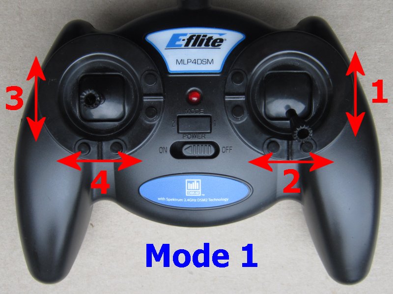
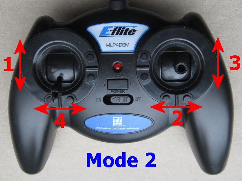
2. Ch3 (Elevator) should be normal, not reversed.
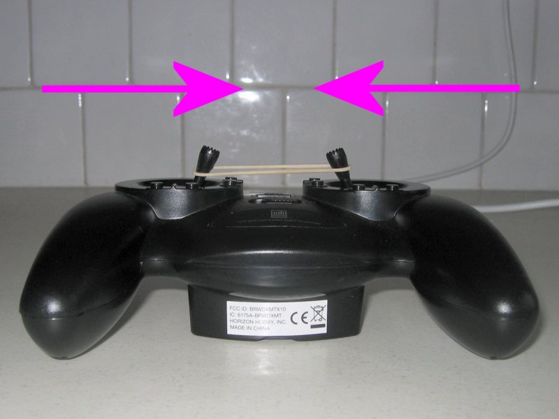
3. Hold left/right sticks (Ch2/4) in towards middle of Tx (use rubber band if necessary).
4. Switch Receiver on and wait for the Led to flicker very fast.
5. Center all sticks.
Make choices:
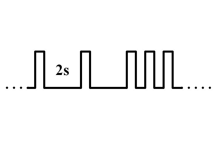
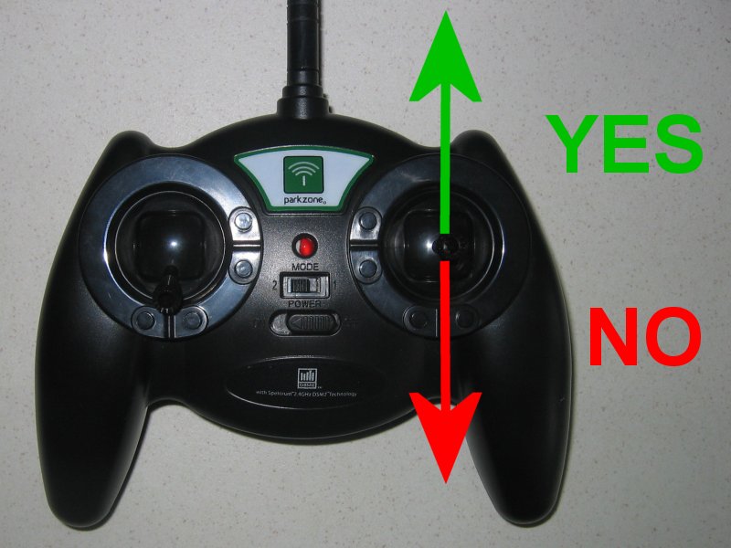
6. The led flashes the setting for the first 'Level' (eg: 1-flash = Motor output 'H').
7. Yes = push the Ch3 (Elevator) stick forward (to top of Tx) to accept this option and advance to next Level.
8. No = pull the Ch3 (Elevator) stick back (to bottom of Tx) to see next option for same Level.
9. Continue through all Levels until Led comes on solid.
Settings are saved automatically at the end so switch off at any time to abort.
Say 'yes' to every item to just see what is currently set.
|
Changing 'P2' from Ch4 to Ch5. Level 1: 3-flash = P Level 2: 2-flash = P2 Level 3: 1-flash = Servo Level 4: 5-flash = Ch5 |
4. DX3:
1. Use full 'brake' to make receiver enter programming mode on startup.
2. Use 3-position Aux channel to make yes/no choices.