
|
|
DT Tx1-M Instructions - v1.2.0
|
|
|
PRODUCT: Tx1
VERSION: 1.2.0
1. DESCRIPTION:
Tx1-M is a DSM2-compatible transmitter module intended to convert traditional joystick transmitters to 2.4GHz.
It is a 'DIY' solution requiring some understanding of electronics and soldering.
It may require a voltage regulator and zener diode to control voltages from the host transmitter.
PPM pulses are converted to channel numbers. Tx1 always transmits 7 channels.
The host transmitter can have 2 to 12 channels. The first 7 PPM pulses are normally used.
2. BINDING:
1. Switch the Rx on in bind mode.
2. Put bind plug on Tx1 Pin1.
3. Switch Tx1 on.
4. Wait for Tx and Rx led to stop flashing.
3. CHANNEL ORDER:
If there is a bind plug on Pin6 when power is applied, the channel order can be changed. Each option flashes twice. Remove plug to save current choice.
1-flash = TAER (JR)
2-flash = AETR (Futaba) - default
3-flash = AERT (Multiplex plane)
4-flash = AERT6A (Multiplex plane dual aileron)
5-flash = same as Mode3 but Ch3/5 swopped (allows use of 4ch receivers with Aileron2/Elevon2 mixing)
6-flash = AERCT (Multiplex heli)
TAER= Throttle, Aileron, Elevator, Rudder, Ch5, Ch6, Ch7.
AETR=Aileron, Elevator, Throttle, Rudder, Ch5, Ch6, Ch7.
AERT=Aileron, Elevator, Rudder, Throttle, Ch5, Ch6, Ch7.
AERT6A=Aileron, Elevator, Rudder, Throttle, Ch6, Aileron2, Ch7.
AERCT=Aileron(Roll/Ch2), Elevator(Pitch/Nick/Ch3), Rudder(Yaw/Ch4), Collective(Ch5), Throttle(Ch1), Ch6, Ch7.
| MODE | 1 JR |
2 Futaba |
3 MPX Plane |
4 MPX Plane Dual aileron |
5 MPX Plane Ch3/5 swop |
6 MPX Heli |
|---|---|---|---|---|---|---|
| Pulse 1 | Channel 1 | Channel 2 | Channel 2 | Channel 2 | Channel 2 | Channel 2 |
| Pulse 2 | Channel 2 | Channel 3 | Channel 3 | Channel 3 | Channel 5 | Channel 3 |
| Pulse 3 | Channel 3 | Channel 1 | Channel 4 | Channel 4 | Channel 4 | Channel 4 |
| Pulse 4 | Channel 4 | Channel 4 | Channel 1 | Channel 1 | Channel 1 | Channel 5 |
| Pulse 5 | Channel 5 | Channel 5 | Channel 5 | Channel 6 | Channel 3 | Channel 1 |
| Pulse 6 | Channel 6 | Channel 6 | Channel 6 | Channel 5 | Channel 6 | Channel 6 |
| Pulse 7 | Channel 7 | Channel 7 | Channel 7 | Channel 7 | Channel 7 | Channel 7 |
| Pulse 8-12 | Not normally used | Not normally used | Not normally used | Not normally used | Not normally used | Not normally used |
4. SUBTRIM:
Some transmitters have different neutral positions to what Tx1 expects. This seems to be most noticeable on helicopters like the MCPx. These may require trim offset. This can be done in the host Tx (eg: -65 subtrim on a Futaba, -8% on a Sanwa) or in Tx1.
If there is a bind plug on Pin4 when power is applied, the neutral position of all channels can be changed. Each option flashes twice. Remove plug to save current choice.
1-flash = ---
2-flash = --
3-flash = -
4-flash = default
5-flash = +
6-flash = ++
7-flash = +++
5. SKIP PPM PULSES:
By default, Tx1 uses the 1st 7 PPM pulses from the host Transmitter.
Up to 6 pulses can be skipped/ignored so that Tx1 can be made to transmit higher channel numbers.
One way of using this feature is with 2 Tx1's with each transmitting different channels to different receivers.
After skipping over the chosen number of channels, the next 7 will be transmitted as 'Ch1-7'.
The channel allocation simply matches the PPM pulse order (no sorting).
If there is a bind plug on Pin5 when power is applied, the number of pulses to skip can be changed. Each option flashes twice. Remove plug to save current choice.
1-flash = skip 1 pulse (ie: use pulses 2-8)
2-flash = skip 2 pulses (ie: use pulses 3-9)
3-flash = skip 3 pulses ...
4-flash = skip 4 pulses
5-flash = skip 5 pulses
6-flash = skip 6 pulses
7-flash = disabled (0 pulses skipped) - default
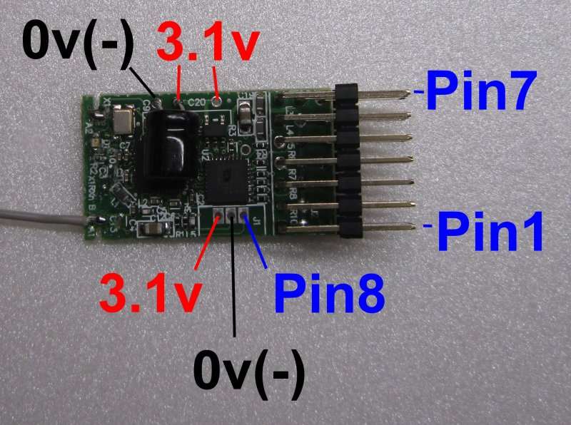
6. TECHNICAL DETAILS:
Tx1 can be powered by 3.2-10v.
The PPM input to the signal Pin7 must be 2.1v to 3.6v (max) when high.
The PPM input must be below 0.8v when low.
Pin7 'floats' so needs active (strong) highs and lows.
The PPM signal can idle high or low.
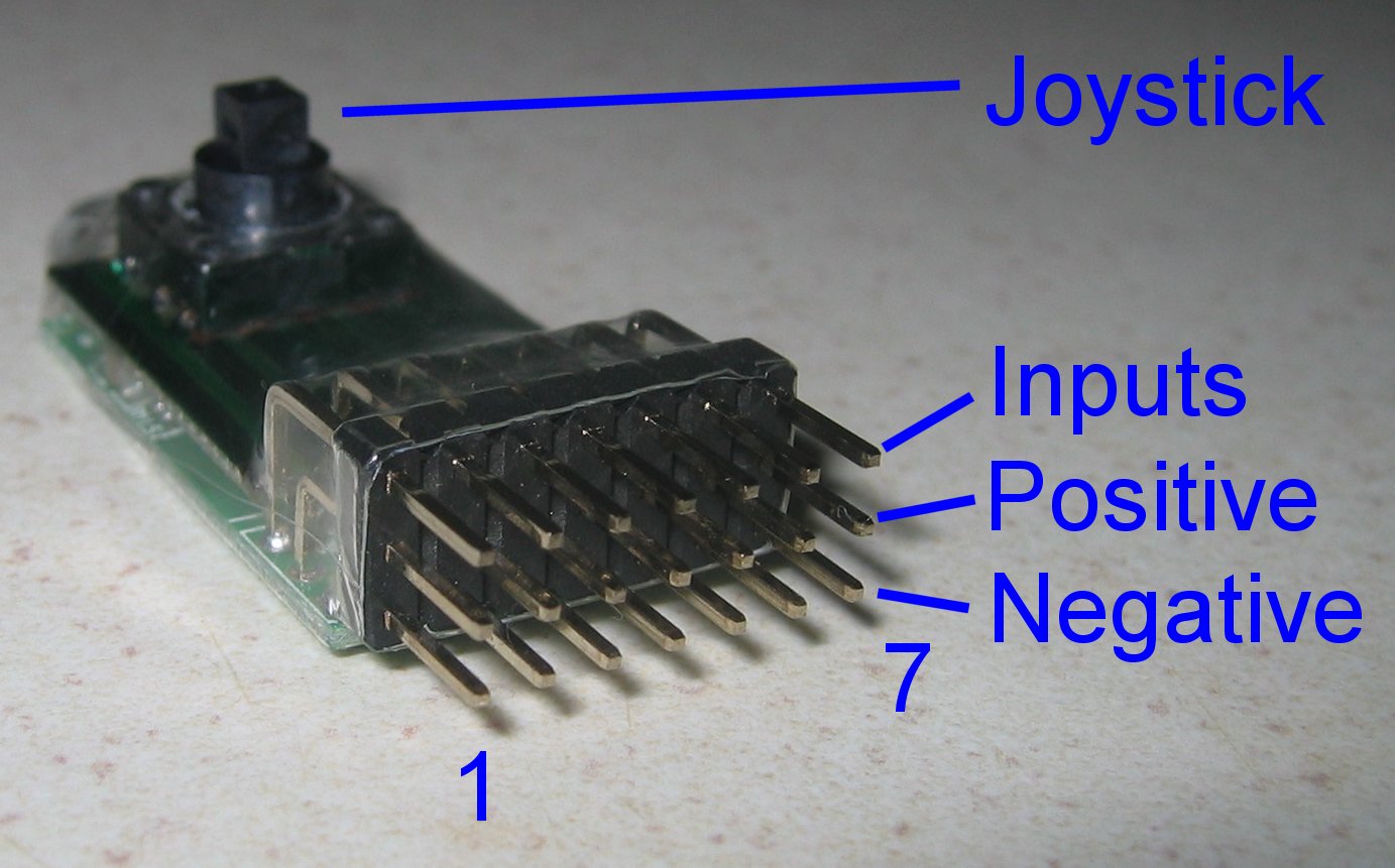
7. EXAMPLE PPM CONNECTION:

|
8. PIN CONNECTIONS:
| Pin number | Normal usage | Startup |
|---|---|---|
| Pin1 | - | Bind |
| Pin2 | - | - |
| Pin3 | - | - |
| Pin4 | - | Subtrim |
| Pin5 | - | Pulses to skip |
| Pin6 | - | PPM channel order |
| Pin7 | PPM input | - |
| Pin8 | LED2 | LED2 |
LED2 is an output to drive a remote led. Connect led between Pin8 and Negative. Pin8 is 3.1v when on and has a 180 ohm current limiting resistor in series with it.