
|
|
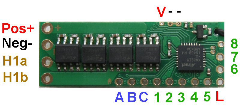
Rx65-22 Instructions (v611)
|
|
|

|
|
1. DEFAULT SETUP
|
Item |
Setting | Details |
|
Purpose: |
Rx65-22 |
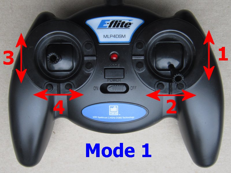
Train with any DT Tx22 transmitter |
|
Red wire positive (+) Black wire negative (-) |
Battery |
3-13v Observe polarities |
|
H1 output |
Motor Ch1 |
Integrated forward/reverse ESC for brushed motors Center off |
|
F1 output 'A' (P9) |
Front Light |
Auto action, 0v when on, disconnected when off |
|
F2 output 'B' (P10) |
Rear Light |
Auto action, 0v when on, disconnected when off |
|
F3 output 'C' (P11) |
On/Off Ch5 |
Start disconnected, 0v (on) when channel is Low Momentary action |
|
P1 |
Front Light |
Auto action, 3.3v when on, 0v off; LED2 enabled |
|
P2 |
Rear Light |
Auto action, 3.3v when on, 0v off |
|
P3 |
On/Off |
Ch3, Idle high (3.3v), 0v when channel is Low, Momentary action |
|
P4 |
On/Off |
Ch3, Idle high (3.3v), 0v when channel is High, Momentary action |
|
P5 |
On/Off |
Ch5, Start high, toggle when channel is Low, Latching action |
|
P6 |
On/Off |
Ch5, Idle low (0v), 3.3v when channel is Low, Momentary action |
|
P7 |
On/Off |
Ch4, Idle high (3.3v), 0v when channel is Low, Momentary action |
|
P8 |
Servo |
Ch1, Standard servo |
|
Selecta |
Enabled |
Up to 12 locos can be associated with the Selecta switch on Tx22 The selector switch position is memorised during binding. Rx 'holds' motor setting when deselected (suitable for continuous loop) Led 2-flash if loco is currently not selected |
|
L input |
Auto-detect |
Monitors battery when used with a voltage booster |
|
Arming |
Enabled |
Ch1 to center position (off) |
|
Low Voltage Cutoff |
Enabled |
Led 5-flash if triggered (LVC) |
| Cruise control | Enabled |
Outputs 'hold' last position on signal loss/Tx switched off |
| Inactivity Sleep | Enabled |
Invoked after 1hour, Switch Rx off and on to restart |
|
Battery Voltage flashes |
Enabled |
Press Bind button (Ch5) briefly and count flashes as described here Flashes appear on LED2 output (P1) |
2. CONNECTIONS:
Pads are in different positions but the connections are very similar to the previous version Rx65-22
The minimum connections are Battery to +/- and Motor to H1a/H1b.
3. BINDING
Bind once:
1. Switch Rx on and wait ~20s until led flickers fast.
2. Switch Tx on in bind mode.
3. Rx led should flash slowly; wait for it to go solid.
Change distance between Tx/Rx if binding does not work.
4. LED:
Led On = perfect reception (real-time indicator).
1 flash = Scanning (~2sec between flashes; no signal or not bound if never stops).
5 flash = LVC/Brownout (voltage went too low; check battery/motor load).
5. PAPERCLIP CHANGES:
The following changes can be made by simply shorting two pads together (eg: with a paperclip):
1. Perform a 'Hard reset' (factory reset).
2. Change motor control between 'low off' and 'center off'.
3. Enable/disable LVC (eg: when using Nicads, NiHMs, LiFe cells).
4. Enable/disable Selecta.
5. Enable/disable Cruise Control/Failsafe.
6. Enable/disable the Menu feature.
'Paperclip' changes
6. PROGRAMMING:
This receiver has many other options that are described on the features page.
These are changed using a technique called 'programming': v611.