
|
|
DT Receiver - Rx41 Instructions - v3.4.x
|
|
1. GENERAL:
3-6v may be connected with correct orientation to +/- points.
The Rx is not insulated so take care to avoid short circuits.
The PCB is thin so do not bend it or exert great force on it.
2. LED:
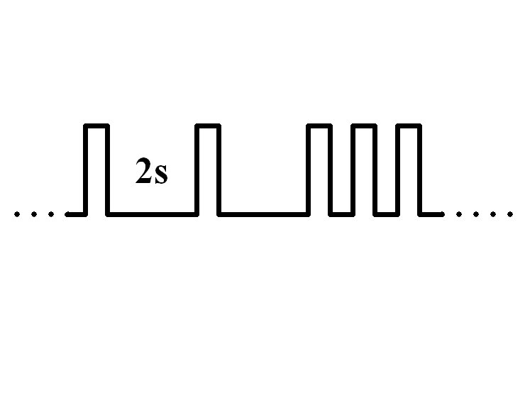
Led On = perfect reception (real-time indicator).
1 flash = Scanning (~2sec between flashes; wrong model if never stops).
2 flash = Brownout (receiver voltage went too low; check battery/servo load).
3. FAILSAFE:
Outputs are not driven (do nothing) on startup and while scanning.
Outputs 'hold' on short signal losses (<1sec) and then do nothing (>1s).
4. BINDING:
1. Switch Rx on and wait ~20s until led flickers fast.
2. Switch Tx on in bind mode and Rx led should flash slowly and then go solid.
3. Change distance between Tx/Rx if binding does not work.
5.1 'ACTUATOR' OUTPUT:
The ACT output will normally be used for an actuator (11ohms or more)
It defaults to Ch2/Aileron but can be changed to Ch3/Elevator or Ch4/Rudder.
It can also be used as a 0.4A forward/reverse ESC for a brushed motor (usually used with Ch3/Elevator).
5.2 BRUSHED ESC:
Set Ch1/Throttle throws to 100%.
Close throttle to arm the ESC.
5.3 LOW VOLTAGE CUTOFF:
A 3.0v LVC is enabled by default.
The ESC will rearm if the throttle is closed briefly.
The led will have a 2-flash if LVC is triggered.
5.4 'ALTERNATE' OUTPUT:
The brushed ESC can be diabled and the output used to drive a servo or brushless ESC.
6.1 PROGRAMMING:
|
|
|
1. Switch Transmitter on.
2. Hold left/right sticks (Ch2/4) in towards middle of Tx.
3. Switch Receiver on and wait for the Led to flicker very fast.
4. Center all sticks.
5. The led flashes the setting for the first 'Level' (eg: 1-flash = LVC disabled, 2-flash = LVC enabled).
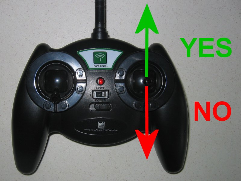
6. Yes = push the Ch3 (Elevator) stick forward (to top of Tx) to accept this and advance to next Level.
7. No = pull the Ch3 (Elevator) stick back (to bottom of Tx) to see next option for same Level.
8. Continue through all Levels until Led comes on solid.
9. Settings are saved automatically at the end so switch off at any time to abort.
10. Say 'yes' to every item to just see what is currently set.
|
This example shows how to set up twin-steer mix on Rx31d. Although not relevant to this receiver the technique is the same: Level 1: 1-flash NO, 2-flash NO, 3-flash YES = Option 3 (25%) & move to next level Level 2-6: YES to all. |
6.2 PROGRAM LEVELS / NUMBER OF FLASHES:
Level 1: Low Voltage Cutoff (brushed ESC only)
1 = Disabled
2 = Enabled (Default)
Level 2: Pad B output
1 = Pad B drives the on-board FET for brushed ESC (Default)
2 = Pad B drives an external brushless ESC or servo
Level 3: Actuator channel
1 = Ch2/Aileron (Default)
2 = Ch3/Elevator
3 = Ch4/Rudder