
|
|
DT Receiver - Rx100-T-v503 - Instructions
|
|
|
|
1. DEFAULT SETUP
The configuration of this receiver is to demonstrate/explain some capabilities. Changes would probably have to be made to settings to use it in a vehicle.
* P1 has a special servo type output to give greater control over an external forward/reverse ESC. Channel 3 is used to set direction (forward/reverse). This makes a normal reversable ESC only go one way or the other way until the direction is toggled (a servo will only rotate left or right from center). Channel 1 then only controls how much power is applied in one direction at a time (how far from center a servo rotates). It uses the whole stick movement to achieve full throw for the direction selected. This output is for vehicles that don't change direction very often and can benefit from fine motor control (eg: boats, trains).
* P2 has a servo steering output (eg: boat/car).
* P3-8 have 'car' type led outputs. They assume Ch3 would be used for throttle with center off.
All outputs can be customised / re-configured.
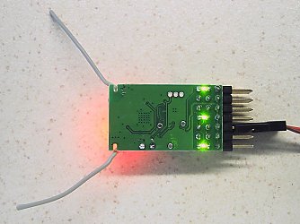
The 'T' version has 3 extra leds on the bottom to help experiment with programming.
| Output | Type | Channel | Other |
| P1: | Servo or fwd/reverse ESC ('full stick' throttle) | Ch1 | Ch3 sets 'direction' when throttle is closed |
| P2: | Servo | Ch2 steering | |
| P3: | Brake led | Ch3 (auto) | |
| P4 (Green led): | Left indicator Led |
Ch4 left <1s activate left led Ch4 left >2s toggle Hazards on/off |
Ch2 steer (auto off) Ch2 trim picked up on startup |
| P5: | Reverse led | Ch3 (auto) | |
| P6 (Green led): | Flasher Led (0.5s) | Ch4 right >2s toggle on/off | |
| P7 (Green led): | Right indicator Led | Ch4 right <1s activate right led | Ch2 steer (auto off) |
| P8: | Led on/off | Ch1 up on | |
| Arming/Activation: | Low-stick to enable | Ch1 | |
|
LVC: (Low Voltage Cutoff <3.0v) |
Low-stick to acknowledge Brake light ON; outputs OFF 'LED2' 2-flash |
Ch1 | |
|
LED2: (external LED to show receiver activity) |
P4 |
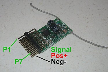
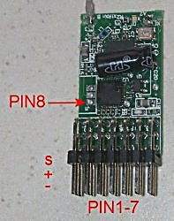
2. CONNECTIONS:
Servos:
Servo are plugged on in the normal manner (negative- on bottom of board).
LEDs with 1S Lipo:
Led's driven from P outputs only require a current limiting resistor (8mA max).
A 180 ohm resistor is built into the receiver.
Connect led between Positive+ and the 'signal' pin.
LEDs with 5-6v:
'P' outputs are 3.1v when 'off' and 0v when 'on'. So when used with higher voltages, the leds driven from P outputs also need diodes to reduce the voltage. This is because 5 or 6v is high enough above the 3.1v output to make Leds conduct even when P outputs are 'off'.
GRAIN of WHEAT:
Grain of Wheat bulbs usually draw >8mA so are not suitable for use with P outputs (unless buffered with a transistor).
3. CHANGING OUTPUTS:
All outputs can be customised / re-configured:
PROGRAMMING
4. GENERAL:
Rx100-T is intended for testing how v5 programming works.
It comes with 3 green leds installed on P4, P6 and P7.
It is easy to connect servos for testing.
5. LED:
Led On = perfect reception (real-time indicator).
1 flash = Scanning (~2sec between flashes; wrong model if never stops).
2 flash = Brownout (receiver voltage went too low; check battery/servo load).
6. FAILSAFE:
Outputs are not driven (do nothing) on startup and while scanning.
Outputs 'hold' on short signal losses (<1sec) and then do nothing (>1s).
7. BINDING:
1. Switch Rx on and wait ~20s until led flickers fast.
2. Switch Tx on in bind mode and Rx led should flash slowly and then go solid.
3. Change distance between Tx/Rx if binding does not work.