
|
DT Tx2 - v2.0.0 Instructions
|
Tx2 is a reprogrammed receiver which is used to make a 2.4GHz transmitter compatible with other DSM2 receivers.
It has 4 primary 'modes' to help you find the most suitable for your needs.

|
EXAMPLE: Tx21 and Tx23 1 and 3-train controller kits using Mode1 and Mode3 of Tx2 respectively. Controls for Speed, Direction, Inertia, Front and Rear lights. |

|
EXAMPLE: Coax heli and cheap plane transmitters Proportional or switched control of up to 7 channels |
PRODUCT: Tx2
GENERAL INFORMATION:
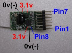
 (3.1v is source for Vref) |
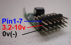
 (1-2S lipo or 3-6 AA or 9v PP3) |
PIN FUNCTIONS:
(* = Default mode)
| Signal Pin |
MODE 1* 1 TRAIN |
MODE 2 5ch |
MODE 3 3 TRAINS |
MODE 4 7ch |
|---|---|---|---|---|
| Pin1 | Ch1 analogue (Motor) | Ch1 analogue | Ch1 analogue (Motor1) | Ch1 analogue |
| Pin2 | Ch2 analogue | Ch2 analogue | Ch2 analogue (Motor2) | Ch2 analogue |
| Pin3 | Ch3 analogue (Direction) | Ch3 analogue | Ch3 analogue (Direction1) | Ch3 analogue |
| Pin4 | Inertia analogue | Ch4 analogue | Inertia analogue | Ch4 analogue |
| Pin5 | Ch5 digital + BIND | Ch5 digital + BIND | Ch5 analogue (Direction2) + BIND | Ch5 analogue + BIND/REVERSE |
| Pin6 | REVERSE | REVERSE | Ch6 analogue (Motor3) | Ch6 analogue + MIX_CH + MIX%1 |
| Pin7 | TRIM | TRIM | Ch7 analogue (Direction3) + TRIM | Ch7 analogue + TRIM + MIX%2 |
| LED on PCB | LED1 output | LED1 output | LED1 output | LED1 output |
| Pin8 | LED2 output + MODE | LED2 output + MODE | LED2 output + MODE | LED2 output + MODE |
ANALOGUE INPUTS:
Tx2 is designed to have joysticks and potentiometers connected to create proportional channel movements.
The proportional movements come from the division of a reference voltage by each pot.
Inputs that are capable of this are called 'analogue' (= infinitely adjustable).
Channel positions will be random if analogue pins are left unconnected (they 'float').
REFERENCE VOLTAGE:
Tx2 has a 3.1v reference voltage (Vref) but the analogue inputs can only measure up to 2.1v.
It is easy to create a 50% voltage with 2 equal resistors so this is necessary to create a 1.55v reference.
For example, a 10k pot creates a proportional 0-1.55v range when in series with a 10k resistor.
The pot and resistor can be any equal value between 4k7 and 100k but 10k for both is a common choice (10k = 10 000 ohms).
DIGITAL INPUTS:
Some inputs are classed as 'digital' which means they can only have two states, High (3.1v) or Low (0v).
When nothing is connected to digital inputs, their internal resistors pull them up to 3.1v.
A switch or bind plug is used to pull them Low (0v).
THROWS:
Tx2 uses 10bit resolution (1024 steps max).
150% throws: 0-1.55v = 0-1023 = 0.9-2.1ms servo pulse (Pins2-7).
100% throws: 0-1.55v = 171-852 = 1.1-1.9ms servo pulse (Pin1 motor).
LED:
If Tx2 is built into a box, Pin8 can drive an external 'LED2'.
MAXIMUM VOLTAGES:
PIN 1-8 Analogue input: 0-1.55v.
PIN 1-8 Digital input: 0v or 3.1v.
PIN 1-8 Max input: 3.6v.
Battery: 3.2-10v.
Low voltage protection: NO.
BIND:
Receivers have to be bound to Tx2 for them to accept its signals:
1. Get the receiver into bind mode (led flashing fast).
2. Press and hold the BIND button, switch Tx2 on and then release the BIND button.
3. The Led will flash slowly for a few seconds.
TRIMS:
Trims change in steps of 4 and can shift the entire range without restriction.
One button is used to change trims of any channel:
1. Move joystick/pot/switch to 'center' position (0.8v).
2. Press and hold TRIM button and the Led will go off.
3. Move joystick/pot/switch 'full throw' in direction required for trim change (0v or 1.55v).
4. Led will flash and Trim will change '1 click' per half second.
5. Trims have 128 'clicks' each way and the Led will stay on for 2 seconds when the trim value returns to center.
6. Release TRIM button to save.
REVERSE:
One button is used to reverse any channel:
1. Move joystick/pot/switch to 'center' position (0.8v).
2. Press and hold REVERSE button and the Led will go off.
3. Move joystick/pot/switch to 'full UP' (1.55v) and the channel will change to NORMAL direction immediately.
4. Move joystick/pot/switch to 'full DOWN' (0v) and the channel will change to REVERSE direction immediately.
5. Release REVERSE button to save.
MODE:
Pin8 is used to change the Mode:
1. Connect Pin8 to 3.1v and switch on.
2. LED1 will flash the current mode twice
3. While Pin8 continues to be connected to 3.1v, the LED will scroll through the options.
4. Release Pin8 to save.

TRAIN FEATURES:
'MOTOR' CHANNEL:
The motor channel controls speed and uses different channel numbers to control up to 7 trains individually.
It will normally be 'center off' if the Direction feature is not used.
'DIRECTION' CHANNEL:
The direction channel will only have any effect with ESC's that require a second channel to set Fwd/Rev direction.
DT receivers with integrated ESCs can be used with or without the Direction feature.
INERTIA / BRAKE:
The inertia control modifies the Motor channel to smooth out changes in speed (sometimes called 'momentum').
It ranges from having no effect to making the speed ramp up/down progressively over up to 30 seconds.
The Led flickers while a transition is in progress and reducing the inertia setting while in motion has a braking effect.
LIGHTS:
The Direction channel can be used to switch up to 4 lights on and off with DT receivers.
MODE 1:
Mode 1 is intended for trains.
Note:
1. The TRIM feature will normally only be used if the motor control knob needs 'centering' more accurately.
2. The MODE change switch will not normally be needed.
3. The REVERSE feature will not normally be used.
| Signal Pin |
Function |
|---|---|
| Pin1 | Ch1 analogue (Motor) |
| Pin2 | Ch2 analogue |
| Pin3 | Ch3 analogue (Direction) |
| Pin4 | Inertia analogue |
| Pin5 | BIND + Ch5 digital |
| Pin6 | REVERSE |
| Pin7 | TRIM |
| LED on PCB | LED1 output |
| Pin8 | LED2 output + MODE |
WIRING DIAGRAM:
1 train controller (with switches for Direction and Ch2)
1 train controller (with switch for Direction)
1 train controller (with pot for Direction)
PIN 1:
Pin1 is expected to control motor speed using Channel 1.
Changes are smoothed by the Inertia feature.
PIN 2:
Pin2 can, for example, be used with a 3-way switch to control lights or a servo using Channel 2.
PIN 3:
Pin3 is expected to control motor direction using Channel 3 on receivers/ESCs that use a separate Direction channel.
PIN 4:
Pin4 controls Inertia.
Its value is not transmitted; it is used to smooth Channel 1.
PIN 5:
Pin5 is digital and has an internal pullup.
It requires a pushbutton switch or bind plug to pull down to 0v (=active).
It controls BIND on startup and Ch5 in normal use.
Ch5 can only be at one extreme (position 0) or the other (position 1023) but can be used to control a light or servo.
Ch5 cannot be reversed or trimmed.
PIN 6:
Pin6 is digital and has an internal pullup.
A bind plug is normally used to pull down to 0v (=active).
It controls channel REVERSE.
PIN 7:
Pin7 is digital and has an internal pullup.
A bind plug is normally used to pull down to 0v (=active).
It controls TRIM.
Typically this function will be used to match the ESC's off position with the 'center click' if that type of pot is used.
MODE 2:
Mode 2 is a simple 5 channel transmitter.
Mode 2 is identical to Mode 1 except:
1. Pin4 is transmitted as Channel 4.
2. There is no Inertia function.
| Signal Pin |
Function |
|---|---|
| Pin1 | Ch1 analogue |
| Pin2 | Ch2 analogue |
| Pin3 | Ch3 analogue |
| Pin4 | Ch4 analogue |
| Pin5 | BIND + Ch5 digital |
| Pin6 | REVERSE |
| Pin7 | TRIM |
| LED on PCB | LED1 output |
| Pin8 | LED2 output + MODE |
WIRING DIAGRAM:
5 channels
PINS 1-4:
Pins 1-4 are analogue and require pots to control their values.
PIN 5:
Pin5 is digital and has an internal pullup.
It requires a pushbutton switch or bind plug to pull down to 0v (=active).
It controls BIND on startup and Ch5 in normal use.
Ch5 can only be at one extreme (position 0) or the other (position 1023).
Ch5 cannot be reversed or trimmed.
PIN 6:
Pin6 is digital and has an internal pullup.
It requires a pushbutton switch or bind plug to pull down to 0v (=active).
It controls channel REVERSE.
PIN 7:
Pin7 is digital and has an internal pullup.
It requires a pushbutton switch or bind plug to pull down to 0v (=active).
It controls TRIM.
MODE 3:
Mode 3 is intended for trains.
Note:
1. The TRIM feature will normally only be used if the motor control knob needs 'centering' more accurately.
2. Channel 4 is fixed and cannot be controlled.
3. There is no REVERSE feature.
| Signal Pin |
Function |
|---|---|
| Pin1 | Ch1 analogue (Motor1) |
| Pin2 | Ch2 analogue (Motor2) |
| Pin3 | Ch3 analogue (Direction1) |
| Pin4 | Inertia analogue |
| Pin5 | Ch5 analogue (Direction2) + BIND |
| Pin6 | Ch6 analogue (Motor3) |
| Pin7 | Ch7 analogue (Direction3) + TRIM |
| LED on PCB | LED1 output |
| Pin8 | LED2 output + MODE |
WIRING DIAGRAM:
3 train controller
'MOTOR' CHANNELS:
Pins 1, 2 and 6 are used with pots to control motor speed with Channels 1, 2 and 6.
When used with conventional ESCs (forward/reverse on one channel), center is usually off.
When used with ESCs that have a separate Direction channel, full rotation controls the full power range.
'DIRECTION' CHANNELS:
Pins 3, 5 and 7 are used with switches to control motor direction with Channels 3, 5, and 7.
These pins are only effective with receivers/ESCs that use a separate channel for Direction.
PIN 4:
Pin4 controls Inertia.
Its value is not transmitted; it is used to smooth changes to the motor channels.
PIN 5:
Pin5 requires two switches:
1. A toggle switch selects Direction2 using Channel 5 (between 0.13v and 1.42v).
2. A pushbutton (or 'Bind' plug) pulls Pin5 down to 0v to set BIND.
PIN 7:
Pin7 requires two switches:
1. A toggle switch selects Direction3 using Channel 7 (between 0.13v and 1.42v).
2. A pushbutton (or 'Bind' plug) pulls Pin7 down to 0v to set TRIM.
MODE 4:
Mode 4 is a 7 channel transmitter.
Note:
1. Mode 4 can be used with any number of channels and with or without the 2-channel mixing.
2. Mixing is disabled by default.
| Signal Pin |
Mixing | No Mixing |
|---|---|---|
| Pin1 | Ch1 analogue | Ch1 analogue |
| Pin2 | Ch2 analogue | Ch2 analogue |
| Pin3 | Ch3 analogue | Ch3 analogue |
| Pin4 | Ch4 analogue | Ch4 analogue |
| Pin5 | Ch5 analogue + BIND/REVERSE | Ch5 analogue + BIND/REVERSE |
| Pin6 | Ch6 analogue + MIX_CH + MIX%1 | Ch6 analogue |
| Pin7 | Ch7 analogue + TRIM + MIX%2 | Ch7 analogue + TRIM |
| LED on PCB | LED1 output | LED1 output |
| Pin8 | LED2 output + MODE | LED2 output + MODE |
WIRING DIAGRAMS:
7ch (no mix)
7ch + mix switches
4ch + mix switches
PINS 1-4:
Pins 1-4 are analogue and require pots to control their values.
PIN 5:
Pin5 requires a pushbutton switch to BIND:
1. The pot controls channel 5.
2. The pushbutton pulls Pin5 down to 0v to set BIND/REVERSE.
PIN 6:
Pin6 requires two pushbutton switches if 2-channel mixing is required:
1. The pot controls channel 6.
2. One pushbutton pulls Pin6 down to 0v to set MIX_CH.
3. Other pushbutton pulls Pin6 up to near 3.1v to set MIX%1.
PIN 7:
Pin7 requires two pushbutton switches if 2-channel mixing is required:
1. The pot controls channel 7.
2. One pushbutton pulls Pin7 down to 0v to set TRIM.
3. Other pushbutton pulls Pin7 up to near 3.1v to set MIX%2.
MIXING:
MIX CHANNEL:
The 2 channels to mix can be selected as follows:
1. Press and hold the MIX_CH switch.
2. The LED will flash the current setting twice:
* 1-flash = Ch3+Ch2
* 2-flash = Ch3+Ch2+Reversed (default)
* 3-flash = Ch3+Ch4
* 4-flash = Ch3+Ch4+Reversed.
3. While MIX_CH continues to be held, the LED will scroll through the options.
4. Release MIX_CH to save.
MIX PERCENT '1':
MIX%1 can change the amount by which Channel 3 is mixed:
1. Press and hold the MIX%1 switch.
2. The LED will flash the current setting twice:
* 1-flash = 12.5%
* 2-flash = 25%
* 3-flash = 50% (default)
* 4-flash = 75%
* 5-flash = 100%.
3. While MIX%1 continues to be held, the LED will scroll through the options.
4. Release MIX%1 to save.
MIX PERCENT '2':
MIX%2 can change the amount by which Channel 2 or 4 is mixed:
1. Press and hold the MIX%2 switch.
2. The LED will flash the current setting twice:
* 1-flash = 0%=disabled (default)
* 2-flash = 25%
* 3-flash = 50%
* 4-flash = 75%
* 5-flash = 100%.
3. While MIX%2 continues to be held, the LED will scroll through the options.
4. Release MIX%2 to save.