1. GENERAL:
Rx100 is good for testing how v5 programming works because it is easy to connect servos and leds (between 'signal' and positive+ pins).
Also, any number of receivers can be bound to 1 model memory so many Rx100's can be used simultaneously with another receiver in a vehicle.
(eg: 4 Rx100's operating 4 train points from 1 channel while other channels on the same transmitter operate another receiver on a train).
2. LED:
Led On = perfect reception (real-time indicator).
1 flash = Scanning (~2sec between flashes; wrong model if never stops).
2 flash = Brownout (receiver voltage went too low; check battery/servo load).
3. FAILSAFE:
Outputs are not driven (do nothing) on startup and while scanning.
Outputs 'hold' on short signal losses (<1sec) and then do nothing (>1s).
4. BINDING:
1. Switch Rx on and wait ~20s until led flickers fast.
2. Switch Tx on in bind mode and Rx led should flash slowly and then go solid.
3. Change distance between Tx/Rx if binding does not work.
|
|
5. DEFAULT SETUP
| Output | Type | Channel | Other |
| P1: | Servo (with 2-channel mix) | Ch2 | 100% mix with P2 |
| P2: | Servo (with 2-channel mix) | Ch3 | No reverse |
| P3: | Left indicator Led |
Ch4 left <1s activate left led Ch4 left >2s toggle Hazards on/off |
Ch2 steer (auto off) Ch2 trim picked up on startup |
| P4: | Right indicator Led | Ch4 right <1s activate right led | Ch2 steer (auto off) |
| P5: | Flasher Led (0.5s) | Ch4 right >2s toggle on/off | |
| P6: | Led on/off | Ch3 up <1s toggle on/off | |
| P7: | Led on/off | Ch3 up >2s toggle on/off | |
| Arming/Activation: | Mid-stick to enable | Ch3 | |
|
LVC: (Low Voltage Cutoff <3.0v) |
Mid-stick to acknowledge Brake light ON; outputs OFF 'LED2' 2-flash |
Ch3 | |
|
LED2: (external LED to show receiver activity) |
P3 |
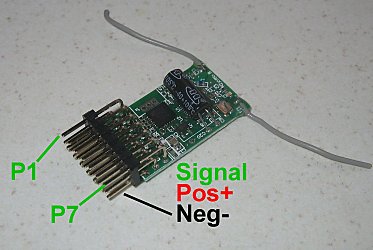
6. CONNECTIONS:
Battery to Positve+ and Negtive-.
Led to Signal and Positive+.
7. CHANGING OUTPUTS:
All outputs can be customised / re-configured:
PROGRAMMING